CHAPTER 1
WIND MILL
1.1 Introduction:
In this project we are designed in
horizontal axis windmill. It is a main application is power generation from the
wind .Power generation from horizontal axis windmill used for converting the
power to wind on a torque for rotating shaft. Horizontal axis windmill is a
simplest.
In our project we are generating the
electric current using with the help of revolving blade arrangement. In this
blade arrangement is the mechanical arrangements which are easily rotated. The
rotating speed is depends upon the wind strength. The wind blade arrangement is
coupled with the dynamo. So whenever the wind mill is rotated due to wind, the
dynamo also rotated. The electric power is generated in the dynamo. In this the
motor is fixed for to rotate the wind mill arrangement. And the electric power
is store in the battery.
Wind turbines and solar cells are
excellent devices for the production of power by utilizing the available
natural resources on Mars. However, both wind energy and sunlight are highly
variable source for energy production on the surface of that planet. Power generation with solar panels is
dependent on the availability of sunlight, while for wind turbines it depends
on favorable wind conditions. From the environmental study on Mars1, it can be
seen that in some locations Mars is subjected to regular high-velocity winds.
Mars has local dust storms of at least a few hundred kilometers in extent every
year and, in some years, has great dust storms which can span most of one or
both hemispheres. Global dust storms on Mars absorb solar radiation high in the
atmosphere and thereby both decrease the surface maximum temperature and
increase the upper atmospheric temperature, leading to the high wind speeds on
the planet’s surface. Herein lies the dis-advantage of solar cell application
on the Mars surface, during the dust storm sand particles prevent the sunlight
from reaching the surface. Considering the above mentioned facts, in the
present work a wind turbine has been designed to produce power on Mars
utilizing its wind resources.
The wind is an environmental
friendly energy source that has been used for a very long time for various
applications on Earth such as pumping water, grinding grain, supplying
electricity, etc. For the design of wind turbines on Mars it is necessary to
understand the atmosphere of that planet with comparison to the Earth’s
atmosphere. The Martian atmosphere differs greatly from the Earth’s
environment. In summary, the solar constant for Mars is 597 W/m2 while for
Earth it is 1373 W/m2 (Larsen2. However, for both Mars and Earth there is
significant overlap between the temperature bands, on Mars surface the reported
temperature variation is: −125 0C to +25 0C, while on Earth the corresponding
range is: −80 0C to +50 0C. Furthermore, (1) Mars atmospheric pressure is
approximately 1.0% that of Earth, (2) Mars is much colder than Earth, and (3)
Mars has no liquid water; nonetheless many of its meteorological features are
similar to terrestrial ones. The characteristics of the atmospheres of Mars and
Earth are summarized in.
From Table 1 it can be seen that the
largest difference is in the air pressure and density, a difference that in
turn produces similar differences between the kinematic viscosity, heat
conductivity and heat capacity of the air on both planets, which results into
thinner atmosphere on Mars as compared to the Earth. The thin atmospheric on
Mars would first appear to indicate that it would be an unlikely candidate for wind energy.
However, the extraction potential of power from the wind is a function of
velocity cubed and only proportional to density (Eq. 1), therefore, high winds
can make-up for low density.

Fig. Wind mill
1.2
History:
Man has used wind to power machines for centuries. The
earliest use was most likely as a power source for sail boats, propelling them
across the water. The exact date that people constructed windmills specifically
for doing work is unknown, but the first recorded windmill design originated in
Persia around A.D. 500-900. This machine was originally used for
pumping water then it was adapted for grinding grain. It had vertical sails
made from bundles of lightweight wood attached to a vertical shaft by
horizontal struts. The design, known as the panemone, is one of the least
efficient windmill structures invented. It should be noted that windmills may
have been used in China over 2,000 years ago making it the actual birthplace
for vertical-axis windmills. However, the earliest recorded use found by
archeologists in China is A.D. 1219.
The concept of the windmill spread to Europe after the
Crusades. The earliest European designs, documented in A.D. 1270, had
horizontal axes instead of vertical ones. The reason for this discrepancy is
unknown, but it is likely a result of two factors. First, the European
windmills may have been patterned after water wheels that had a
horizontal. The
water wheel had been known in Europe for long before this. Second, the
horizontal axis design was more efficient and worked better. In general, these
mills had four blades mounted on a central post. They had a cog and ring gear
that translated the horizontal motion of the central shaft into vertical motion
for the grindstone or wheel which would then be used for pumping water or
grinding grain.
The European millwrights improved
windmill technology immensely over the centuries. Most of the innovation came
from the Dutch and the English. One of the most important improvements was the
introduction of the tower mill. This design allowed for the mill's blades to be
moved into the wind as required and the main body to be permanently fixed in
place. The Dutch created multi-story towers where mill operators
could work and also live. The English introduced a number of automatic controls
that made windmills more efficient.
During the pre-industrial world, windmills were the electric
motors of Europe. In addition to water pumping and grain grinding, they were
used for powering saw mills and processing spices, dyes, and tobacco. However,
the development of steam power during the nineteenth century, and the uncertain
nature of windmill power resulted in a steady decline of the use of
Large
wind mill structures. Today, only a small fraction of the windmills that used
to power the world are still standing.
Even as larger windmills were abandoned, smaller fan-type
windmills were thriving. These windmills were used primarily for pumping water
on farms. In America, these designs were perfected during the nineteenth century.
The Holladay windmill was introduced in
1854 followed by the Aerometer and Dumpster designs. The
latter two designs are still in use today. In fact, between 1850 and 1970 in the United States over six million were
constructed.

Fig. 1.1 Schematic Diagram of mind
mill
CHAPTER 2
WIND MILL DESIGN
2.1
Types and Explanation of wind mill
There are two classes of windmill, horizontal axis and vertical
axis. The vertical axis design was popular during the early development of the
windmill. However, its inefficiency of operation led to the development of the
numerous horizontal axis designs.


Fig. Types of Wind mills
Of the horizontal axes versions, there are a variety of
these including the post mill, smock mill, tower mill, and the fan mill. The
earliest design is the post mill. It is named for the large, upright post to
which the body of the mill is balanced. This design gives flexibility to the
mill operator because the windmill can be turned to catch the most wind
depending on the direction it is blowing. To keep the post stable a support
structure is built around it. Typically, this structure is elevated off the
ground with brick or stone to prevent rotting.
The post mill has four blades mounted on a central post. The
horizontal shaft of the blades is connected to a large break wheel. The break
wheel interacts with a gear system, called the willower, which rotates a
central, vertical shaft. This motion can then be used to power water pumping or
grain grinding activities.
The smock mill is similar to the post mill but has included
some significant improvements. The name is derived from the fact that the body
looks vaguely like a dress or smock as they were called. One advantage is the
fact that only the top of the mill is moveable. This allows the main body
structure to be more permanent while the rest could be adjusted to collect wind
no matter what direction it is blowing. Since it does not move, the main body
can be made larger and taller. This means that more equipment can be housed in
the mill, and that taller sails can be used to collect even more wind. Most
smock mills are eight sided although this can vary from six to 12.
Tower mills are further improvements on smock mills. They
have a rotating cap and permanent body, but this body is made of brick or
stone. This fact makes it possible for the towers to be rounded. A round
structure allows for even larger and taller towers. Additionally, brick and
stone make the tower windmills the most weather resistant design. While the
previous windmill designs are for larger structures that could service entire
towns, the fan-type windmill is made specifically for individuals. It is much
smaller and used primarily for pumping water. It consists of a fixed tower
(mast), a wheel and tail assembly (fan), a head assembly, and a pump. The masts
can be 10-15 ft (3-15 m) high. The number of blades can range from four to 20
and have a diameter between 6 and 16 ft (1.8-4.9 m).
2.2
Raw materials:
Windmills can be made with a variety of materials. Post
mills are made almost entirely of wood. A lightweight wood, like balsa wood, is
used for the fan blades and a stronger, heavier wood is used for the rest of
the structure. The wood is coated with paint or a resin to protect it from the
outside environment. The smock and tower mills, built by the Dutch and British
prior to the twentieth century, use many of the same materials used for the
construction of houses including wood, bricks and stones.
The main body of the fan-type mills is made with galvanized steel. This process of treating steel makes it weather resistant
and strong. The blades of the fan are made with a lightweight, galvanized steel
or aluminum. The pump is made of bronze and brass that inhibits freezing.
Leather or synthetic polymers are used for washers and o-rings.
A wind turbine consists of three basic parts: the tower,
the nacelle, and the rotor blades. The tower is either a steel lattice tower
similar to electrical towers or a steel tubular tower with an inside ladder to
the nacelle.

The first step in constructing a wind turbine is erecting the
tower. Although the tower's steel parts are manufactured off site in a factory,
they are usually assembled on site. The parts are bolted together before
erection, and the tower is kept horizontal until placement. A crane lifts the
tower into position, all bolts are tightened, and stability is tested upon
completion.
Next, the fiberglass nacelle is installed. Its inner workings—main drive shaft, gearbox, and blade pitch and yaw controls—are assembled and mounted onto a base frame at a factory. The nacelle is then bolted around the equipment. At the site, the nacelle is lifted onto the completed tower and bolted into place.
Next, the fiberglass nacelle is installed. Its inner workings—main drive shaft, gearbox, and blade pitch and yaw controls—are assembled and mounted onto a base frame at a factory. The nacelle is then bolted around the equipment. At the site, the nacelle is lifted onto the completed tower and bolted into place.
Most towers do not have guys, which are cables
used for support, and most are made of steel that has been coated with a zinc
alloy for protection, though some are painted instead. The tower of a typical
American-made turbine is approximately 80 feet tall and weighs about 19,000
pounds.
The nacelle is a strong, hollow shell that contains the
inner workings of the wind turbine. Usually made of fiberglass, the nacelle
contains the main drive shaft and the gearbox. It also contains the blade pitch
control, a hydraulic system that controls the angle of the blades, and the yaw
drive, which controls the position of the turbine relative to the wind. The
generator and electronic controls are standard equipment whose main components
are steel and copper. A typical nacelle for a current turbine weighs
approximately 22,000 pounds.
The most diverse use of materials and the most experimentation
with new materials occur with the blades. Although the most dominant material
used for the blades in commercial wind turbines is fiberglass with a hollow
core, other materials in use include lightweight woods and aluminum. Wooden
blades are solid, but most blades consist of a skin surrounding a core that is
either hollow or filled with a lightweight substance such as plastic foam or
honeycomb, or balsa wood. A typical fiberglass blade is about 15
meters in length and weighs approximately 2,500 pounds.
Wind turbines also include a utility box, which converts
the wind energy into electricity and which is located at the base of the tower.
Various cables connect the utility box to the nacelle, while others connect the
whole turbine to nearby turbines and to a transformer.

Fig. 2.2 Raw materials wind mill
2.3
The Manufacturing process:
Windmills are always erected on site using pre-made parts.
The following description relates to the fan-type windmill.

An example of a windmill
built in 1797.
Before consideration can be given to the construction of
individual wind turbines, manufacturers must determine a proper area for the
siting of wind farms. Winds must be consistent, and their speed must be
regularly over 15.5 miles per hour (25 kilometers per hour). If the winds are
stronger during certain seasons, it is preferred that they be greatest during
periods of maximum electricity use. In California's Altamont Pass, for
instance, site of the world's largest wind farm, wind speed peaks in the summer
when demand is high. In some areas of New England where wind farms are being
considered, winds are strongest in the winter, when the need for The nacelle is
a strong, hollow shell that contains the inner workings of the wind turbine,
such as the main drive shaft and the gearbox. It also contains the blade pitch
control, a hydraulic system that controls the angle of the blades, and the yaw
drive, which controls the position of the turbine relative to the wind. A
typical nacelle for a current turbine weighs approximately 22,000 pounds.

Fig. Main Shaft
heating increases the consumption of electrical power. Wind farms work
best in open areas of slightly rolling land surrounded by mountains. These
areas are preferred because the wind turbines can be placed on ridges and
remain unobstructed by trees and buildings, and the mountains concentrate the
air flow, creating a natural wind tunnel of stronger, faster winds. Wind farms
must also be placed near utility lines to facilitate the transfer of the
electricity to the local power plant.
Preparing
the site
Wherever a wind farm
is to be built, the roads are cut to make way for transporting parts. At each
wind turbine location, the land is graded and the pad area is leveled. A concrete foundation
is then laid into the ground, followed by the installation of The underground
cables. These cables connect the wind turbines to each other in series, and
also connect all of them to the remote control center, where the wind farm is
monitored and the electricity is sent to the power company.
Erecting
the tower
Although the tower's
steel parts are manufactured off site in a factory, they are usually assembled
on site. The parts are bolted together before erection, and the tower is kept
horizontal until placement. A crane lifts the tower into position, all bolts
are tightened, and stability is tested upon completion.
Nacelle
The fiberglass
nacelle, like the tower, is manufactured off site in a factory. Unlike the
tower, however, it is also put together in the factory. Its inner workings—main
drive shaft, gearbox, and blade pitch and yaw controls—are assembled and then
mounted onto a base frame. The nacelle is then bolted.

Fig. nacelle
The
utility box for each wind turbine and the electrical communication system for
the wind farm is installed simultaneously with the placement of the nacelle and
blades. Cables run from the nacelle to the utility box and from the utility box
to the remote control center.Around the equipment. At the site, the nacelle is
lifted onto the completed tower and bolted into place.
Making
the tower parts
The tower parts are made from galvanized steel. This process
begins with a roll of coiled sheet metal. The coils are put on a de-spooling
device and fed to the production line. They are run under a straightened to
remove any kinks or twists. The pieces are cut to the appropriate size and
shape. In some cases, pieces may be put on a machine that rolls them and welds
the seam. The ends are passed under a crimping machine and the pieces are moved
to the finishing station. At the finishing station, holes are drilled in the
metal parts at specific places as required by the windmill design. The parts
may also be painted or coated before being arranged in the final windmill kit.
Main parts inside of Wind Turbine
Wind turbines harness the power of the wind and use it to generate
electricity. Simply stated, a wind turbine works the opposite of a fan. Instead
of using electricity to make wind, like a fan, wind turbines use wind to make
electricity. The energy in the wind turns two or three propeller-like blades
around a rotor. The rotor is connected to the main shaft, which spins a
generator to create electricity. This illustration provides a detailed view of
the inside of a wind turbine, its components, and their functionality
Anemometer:
Measures the wind speed and transmits wind speed data to the controller.
Blades:
Lifts and rotates when wind is blown over them, causing the rotor to
spin. Most turbines have either two or three blades.
Brake:
Stops the rotor mechanically, electrically, or hydraulically, in
emergencies.
Controller:
Starts up the machine at wind speeds of about 8 to 16 miles per hour
(mph) and shuts off the machine at about 55 mph. Turbines do not operate at
wind speeds above about 55 mph because they may be damaged by the high winds.
Gear box:
Connects the low-speed shaft to the high-speed shaft and increases the
rotational speeds from about 30-60 rotations per minute (rpm), to about
1,000-1,800 rpm; this is the Rotational speed required by most generators to
produce electricity. The gear box is a costly (and heavy) part of the wind
turbine and engineers are exploring "direct-drive" generators that
operate at lower rotational speeds and don't need gear boxes.
Gear box used in wind energy systems to change low speed high toque power
coming from a rotor blade to high speed low torque power which is used for
generator. It is connected in between main shaft and generator shaft to
increase rotational speeds from about 30 to 60 rotations per minute (rpm) to
about 1000 to 1800 rpm. Gearboxes used for wind turbine are made from superior
quality aluminum alloys, stainless steel, cast iron etc.
The various gear boxes used in wind turbines are
Planetary Gearbox
Helical Gearbox
Worm Gearbox
Generator:
Produces 60-cycle AC electricity; it is usually an off-the-shelf
induction generator.
High-speed shaft:
Drives the generator.
Low-speed shaft:
Turns the low-speed shaft at about 30-60 rpm.
Nacelle:
Sits atop the tower and contains the gear box, low- and high-speed
shafts, generator, controller, and brake. Some nacelles are large enough for a
helicopter to land on.
Pitch:
Turns (or pitches) blades out of the wind to control the rotor speed, and
to keep the rotor from turning in winds that are too high or too low to produce
electricity.
Rotor:
Blades and hub together form the rotor.
Tower:
Made from tubular steel (shown here), concrete, or steel lattice.
Supports the structure of the turbine. Because wind speed increases with
height, taller towers enable turbines to capture more energy and generate more
electricity.
Wind direction:
Determines the design of the Turbine. Upwind turbines like the one shown
hereface into the wind while downwind turbines face away.
Wind vane:
A measure wind direction and communicates with the yaw drive to orient
the turbine properly with respect to the wind.
Anemometers:
Wind speed is the most important factor for determining
the power content in the wind. The power content in the wind is directly
proportional to cube of the wind velocity. Measuring wind speed is important
for site selection. The device which is used for measuring wind speed is called
anemometer. These are usually located on top of the nacelle.
Types of anemometers
The various types of anemometers are used in measuring
wind speed is shown in flow chart below.

Wind vane
Wind vanes are used to measure the wind directions and
communicates with the yaw system to orient the turbine properly with respective
to wind directions, to extract maximum amount of power from wind. Wind turbines
are oriented to upstream wind or down stream wind.
Yaw mechanism:
Orients upwind
turbines to keep them facing the wind when the direction changes. Downwind
turbines don't require a yaw drive because the wind manually blows the rotor
away from it.

Fig. Yaw Mechanism
Yaw motor:
Powers the yaw
drive.
Making
the gearbox
The gearbox is an intricate assembly
made up of various gears, axles, rotors, and wheels. The parts are die cast and
assembled by hand. The are placed in an weather resistant housing that is
designed to accommodate the gearbox parts and the attached wheel and tail
assembly.
Making
the fan
The fan is made up of
a metal rim with slightly curved blades attached. The rim is produced on a
machine that rolls steel strips into circular hoops. A hole is drilled in both
ends, and they are connected with a small clamp and screw after the fan blades are
attached. A center axle is then connected to the rim and attached with small
steel spokes. A typical design will have five pairs of spokes attached a evenly
spaced intervals along the rim. The fan blades and tail are cut from pieces of
sheet metal. The blades are then run through a machine that gives them a slight
curve. They are attached to the metal rim with small bolts and metal clamps.
They are attached in such a way that they can be raised or lowered depending on
the wind conditions.
Final
assembly
The parts of the main body are connected first. They are
bolted together on the ground and then raised up vertically. The outer poles
are joined with the connecting rods. Clamps are bolted at each joint for
stability. After the tower is raised it is loosely bolted to the solid base.
Next stay wires are strung from the frame down to the ground and Attached to
tensioners and ground anchors. When the structure is level, the bolts are
tightened and the structure integrity is tested. In some cases a ladder is built
into the frame design to allow access to the fan on top which makes cleaning an
maintenance easier.
The fan wheel, gearbox, and main shaft are next attached.
The gearbox is first clamped and bolted to the top of the tower. The main shaft
is then inserted into the bottom of the gearbox. Next, the fan and its attached
axle are connected to the gearbox. Finally, the tail section is attached to the
gearbox. The pump is then hooked up to the main shaft and the windmill is
operational.

Fig. All parts after Assembled
Environmental Benefits and
Drawbacks
A wind turbine that produces electricity from inexhaustible
winds creates no pollution. By comparison, coal, oil, and natural gas produce
one to two pounds of carbon dioxide (an emission that contributes to the
greenhouse effect and global warming) per Kilowatt-hour produced. When wind
energy is used for electrical needs, dependence on fossil fuels for this
purpose is reduced. The current annual production of electricity bywind
turbines (3.7 billion kilowatt-hours) is equivalent to four million barrels of
oil or one million tons of coal.
Wind turbines are not completely free of environmental
drawbacks. Many people consider them to be unaesthetic, especially when huge
wind farms are built near pristine wilderness areas. Bird kills have been
documented, and the whirring blades do produce quite a bit of noise. Efforts to
reduce these effects include selecting sites that do not coincide with
wilderness areas or bird migration routes and researching ways to reduce noise.
2.4 Quality Control
Various tests may be done to ensure that each part of the
windmill meets the specifications laid out in the design phase. The most basic
of these are simple visual inspections. These will catch most of the obvious
production flaws. Since windmills are erected by hand, the quality of each part
goes through an additional visual inspection. The quality of workmanship that goes into construction of the windmill
will be primarily responsible for the quality of the finished product. To
ensure that it remains efficient during operation, regular maintenance checks
are necessary.
2.5 The Future
Windmills have changed little over the last hundred years.
In fact, one basic design conceived in the 1870s is still sold today. The major
improvements have come in the types of materials used in construction. This
trend will likely continue in future windmill products. However, the future of
harnessing wind power is not in traditional windmills at all
A method for
operating a windmill where a primary generator is driven by the windmill rotor,
possibly by a gear mechanism, with constant or approximately constant rpm,
disposed between the rotor of the windmill and the primary generator is an
apparatus comprising a slip generator and a frequency converter or resistor
adapted thereto, and which transmits the torque to the primary generator with
an amount of slip, and wherein the power coming from the slip is regenerated to
the electric network via the slip generator and the frequency converter or
Deposited via the resistor as heat at an optional location, wherein the power
coming from the slip between the windmill rotor and the primary generator is
delivered to the electric network by the frequency converter
CHAPTER 3
Working principle of Wind mill
3.1
Horizontal Axis Wind Turbines:
Horizontal-axis wind turbines (HAWT) have the main rotor shaft and
electrical generator at the top of a tower, and may be pointed into or out of
the wind. Small turbines are pointed by a simple wind vane, while large
turbines generally use a wind sensor coupled with a servo motor. Most
have a gearbox, which turns the slow rotation of the blades into a quicker
rotation that is more suitable to drive an electrical generator. Parts of the
wind turbine Blades.

The lifting style wind turbine blade. These are the most efficiently
designed, especially for capturing energy of strong, fast winds. Some European
companies actually manufacture a single blade turbine.
The drag style wind
turbine blade, most popularly used for water
mills, as seen in the old Dutch windmills. The blades are flattened plates
which catch the wind. These are poorly designed for capturing the energy of
heightened winds.
The
rotor:
The rotor is designed aerodynamically to capture the maximum surface
area of wind in order to spin the most ergonomically. The blades are
lightweight, durable and corrosion-resistant material. The best materials are
composites of fiberglass and reinforced plastic.
Rotor blades
Rotor blades are a crucial and elementary part of a
wind turbine. Various demands are placed on them, and they must withstand very
great loads. Rotor blades take the energy out of the wind. They
"capture" the wind and convert its motive energy into the rotation of
the hub. The profile is similar to that of airplane wings. Rotor blades utilize
the same "lift" principle: below the wing, the stream of air produces
overpressure; above the wing, a vacuum. These forces make the rotor rotate.
Today, most rotors have three blades, a horizontal
axis, and a diameter of between 40 and 90 meters. In addition to the currently
popular three-blade rotor, two-blade rotors also used to be common in addition
to rotors with many blades, such as the traditional windmills with 20 to 30
metal blades that pump water in the United States.Over time, it was found that
the three-blade rotor is the most efficient for power generation by large wind
turbines. In addition, the use of three rotor blades allows for a better
distribution of mass, which makes rotation smoother and also provides for a
"calmer" appearance.
The material used
The rotor blades mainly consist of synthetics
reinforced with fiberglass and carbon fibers. The layers are usually glued together
with epoxy resin. Wood, wood epoxy, and wood-fiber-epoxy compounds are less
widely used. One of the main benefits of wooden rotor blades is that they can
be recycled. Aluminum and steel alloys are heavier and suffer from material
fatigue. These materials are therefore generally only used for very small wind
turbines.
Design and profile
Each manufacturer has its own rotor blade concepts
and conducts research on innovative designs; there are many variations that are
quite different. In general, though, all rotor blades are constructed similar
to airplane wings.
Hub
The hub is the center of the rotor to which the
rotor blades are attached. Cast iron or cast steel is used. The hub directs the
energy from the rotor blades on to the generator. If the wind turbines have a gearbox,
the hub is connected to the slowly rotating gearbox shaft, converting the
energy from the wind into rotation energy. If the turbine has a direct drive,
the hub passes the energy directly on to the ring generator.
The rotor blade can be attached to the hub in
various ways: either in a fixed position, with articulation, or as a pendulum.
The latter is a special version of the two-blade rotor, which swings as a
pendulum anchored to the hub. Most manufacturers currently use a fixed hub. It has proved to be sturdy,
reduces the number of movable components that can fail, and is relatively easy
to construct.
Power control
The power that a wind turbine absorbs has to be
controlled. If the wind is too strong, power is reduced to prevent damage to
the system. There are basically two concepts of power regulation.
Stall control
(regulation by flow separation)
Rotor blades with stall control are attached to the
hub at a fixed angle. The profile of the rotor blade is designed to cause
turbulence behind the rotor blade at a particular wind velocity. At the same
time, when the wind is too strong the asynchronous generator also limits power
generation automatically.
Pitch control
This control concept was developed from 1990 up to
2000. Here, each individual rotor blade can be infinitely turned into or out of
the wind. The drive for pitch adjustment is either mechanical (for systems with
an output below 100 kW), hydraulic (starting at 300 kW), or electric (the most
common one, especially for large turbines > 500 kW).
A controller constantly monitors the turbine's power
output. If the wind is too strong, the rotor blades are turned out of the wind
along their axis, generally only by a fraction of the degree. This reduces the
lift, so that the rotor continues to generate power at rated capacity even at
high wind speeds. A gear box magnifies or
amplifies the energy output of the rotor. The gear box is situated directly between the rotor and the generator. A rotor
rotates the generator (which is protected by a nacelle), as directed by the tail
vane.
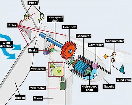
Fig. Parts
of Wind Turbines
The generator produces electricity from the rotation of the
rotor. Generators come in various sizes, relative to the output you
wish to generate. The nacelle is the housing or enclosure That seals and protects
the generator and gear box from the elements. It is easily removed for
maintenance of the wind The tail vane directs the turbine to gather
maximum wind energy.
A wind generator is often named
as wind turbine. The wind turbine looks like a fan, and it works the opposite
of a fan. Unlike a fan, producing wind by spinning the blades with electricity,
wind generator produces mechanical power or electricity by using wind. There
are varieties of wind generators, and each type has different feature and purposes.
In general, small turbines are used to produce mechanical power for certain
tasks (e.g. grinding grain or pumping water). Then, big turbines are often used
to produce bulk power to the electrical grid in
most cases, a wind generator does not stand alone to produce electricity.
Unless a wind generator is used to produce mechanical power for farmer, at
least two or more turbines are planted to produce more electricity.
Feature:
HAWT has its main motor and
electricity generator on top of its tower. The most vivid feature is that the
blades head toward the wind. Most of them have gear box which changes slow
rotation into fast rotation.
- Advantage:
High efficiency because blades
always move perpendicularly to the wind. Tall tower of HAWT allows the turbine
to contact with stronger wind. Therefore, it increases the wind speed by 20%
which is related to increase in power output (37%). Finally, the angles of
blades are adjustable, these maximizes the total amount of power achieving from
same wind.
- Disadvantage:
It is very expensive to build a
tall HAWT since it needs huge blades and supportive tower. Because of the size,
the cost of transportation increases. Therefore, the installation is the
problem.
The HAWT works
In general, annual average wind speeds of 5 meters per second (11 mph)
are required for grid connected applications. Annual average wind speeds of 3
to 4 m/s (7-9 mph) may be adequate for non-connected electrical and mechanical
applications such as battery charging and water pumping. Wind resources
exceeding this speed are available in many parts of the world.The HAWT shaft is
mounted horizontally, parallel to the ground. HAWTs need to constantly align
themselves with the wind using a yaw-adjustment mechanism. The yaw system
typically consists of electric motors and gearboxes that move the
entire rotor left or right in small increments. The turbine's electronic
controller reads the position of a wind vane device (either mechanical or
electronic) and adjusts the position of the rotor to capture the most wind
energy available.

Fig.
HAWT
3.2 Typical lifespan:
The lifespan of a modern turbine is pegged at around 120,000 hours or
20-25 years, however, they are not maintenance free. As they contain moving
components, some parts will need to be replaced during their working life.
Throughout research, the cost of maintenance and parts Replacement is around
the 1 cent USD/AU per kWh or 1.5 to 2 percent annually of the original turbine
cost.
3.3 HAWT Gear boxes:
The gearboxes in
the traditional horizontal axis wind turbines currently have an average life
span of 1.5 years. Replacing these gearboxes can be extremely costly.

Fig. Horizontal Axis Wind Turbine
Gear box
Cost Information
Wind turbines for home use vary in price and greatly depend on your
electricity needs vs. wind availability, but you can expect to pay around
$12,000 to cater for the average home. However, bear in mind that cost can be
greatly offset by renewable energy rebates offered by many governments. The
average price for large, modern wind farms is around 1000 USD per kilowatt
electrical power installed. One extra meter of tower will cost you roughly 1500
USD. A special low wind machine with a relatively large rotor diameter will be more
expensive than a high wind machine with a small rotor diameter.
As you move from a 150 kW machine to a 600 kW machine, prices will
roughly triple, rather than quadruple. The reason is that there are economies
of scale up to a certain point, e.g. the amount of manpower involved in
building a 150 kW machine is not very different from what is required to build
a 600 kW machine. E.g. the safety features, and the amount of electronics
required to run a small or a large machine is roughly the same. There may also
be (some) economies of scale in operating wind parks rather
than individual turbines, although such economies tend to be rather
limited.
Any Power Output Information
Wind turbines for commercial electricity production usual range from
100 kilowatts to 5 megawatts. At the time of writing, the largest wind turbine
in the world had a rotor diameter of 126 m (390 feet) and the potential to
generate enough electricity for 5000 households. For a 600 kW
turbine, the average output is between 1.5 and 2 GWh per year,
depending on wind speed. For every kilowatt hour of electricity produced by
wind energy or other green means, approximately 1.5 pounds of carbon is
prevented from going into the atmosphere if that electricity had been sourced from
coal fired power plants. Carbon dioxide is a major contributor to global
warming induced climate change.
Battery:
The Batteries
have the 2.5-MW windmill is something of a technological leap in an industry
where turbines have gotten bigger and bigger but not necessarily smarter. The
turbine’s software captures tens of thousands of data points each second on
wind and grid conditions and then adjusts production, storing electricity in an
attached 50 kilowatt-hour sodium nickel chloride battery. If say a wind farm is
generating too much electricity to [be] absorbed by the grid—not an uncommon
occurrence in gusty west Texas it can store the electricity in the battery.
When the wind dies down, the electricity can be released from the battery and
put back on the grid. “This provides a path for lowering the cost of energy
even more,” Keith Longtin, general manager of GE’s wind product line, told
Quartz. “We think by being able to integrate the storage into the turbine and
by being able to provide predictable power it’s going to minimize a lot of the
balancing the grid has to do today.”

Inverter:
In Inverters the main device is a transformer. Which
have 12V-0-12V, a common iron core. But instead we use the power input as 220
volts. Then power output as 12 volts. The way the switch differential is power
AC input as 12 volts and output to AC 220 volts.
The 12 volts input power
source is a battery Be Supply into the center tap of the coil 12 volts. This is
now considered a power pack or coil primary. The ends of the wire on both sides
(points A and B) And it will be connected via a 2-way switch to ground.Which if
the switch connected at A point, will cause an electric current number one,
flows from the positive terminal of the battery, into the center tab point.
Then flows up to the top, through the contacts A of the switch to ground. If
the switch is moved from Points of A to the Points of B, would make an electric
current No. 1 has stopped. Because currents will redirect the flow an electric
current is number 2. From the center tap down below. Through contact B of the
switch to ground.
The 2 way switch will be
controlled on-off with the oscillator circuit that as the frequency generator
of 50Hz As a result, switch off – on back and forth between Points of A and B
with a speed of 50 times per second. Makes an electric current No. 1 and No. 2
alternating flow rate of 50 times per second as well. Which current flowing
through the switch all the time like this.
Makes magnetic field
resulting in swelling and shrinkage. And induced across to the 220 volts coil.
Which is now considered to be a output power or secondary coil. The resulting
voltage 220V AC 50Hz frequency winding up this series. The voltage available to
be supplied to the various types of electrical voltage to 220 volts AC to
operate.
Efficiency:
Not all the energy of blowing wind can be harvested, since conservation
of mass requires that as much mass of air exits the turbine as enters it. Betz's law gives the maximal achievable extraction of wind power by a wind turbine
as 59% of the total kinetic energy of the air flowing through the turbine.
Further inefficiencies, such as rotor blade friction and drag, gearbox
losses, generator and converter losses, reduce the power delivered by a wind
turbine. Commercial utility-connected turbines deliver 75% to 80% of the Betz
limit of power extractable from the wind, at rated operating speed.
Efficiency can decrease slightly over time due to wear. Analysis of 3128
wind turbines older than 10 years in that half of the turbines had no decrease,
while the other half saw a production decrease of 1.2% per year.
CHAPTER 4
DESCRIPTION
4.1
Back Ground of The Invention:
The invention concerns a
method for operating windmills where a primary generator is driven by the
windmill rotor, possibly with a gear mechanism, with constant or approximately
constant rotational speed. The invention also concerns a windmill where a
primary generator is driven by the rotor of the windmill, possibly with a gear
mechanism, with constant or approximately constant rotational speed.
It is known that certain
optional benefits may be achieved in windmills if one may establish operation
with variable rpm.
Many modern types of windmills are provided
with a directly network connected asynchronous generator. This kind of
generator has significant advantages. Even if certain adjustments in the
winding have been made, the directly network connected asynchronous generator
is in principle just a directly network connected asynchronous motor driven at
an super synchronous rpm by an external energy source. An asynchronous motor
with short-circuited rotor is the most simple and robust form of electric
motor, and the asynchronous generator has the same advantages. The only wear parts
are constituted by the bearings. Large production numbers on the motor side
implies that the price per kW is the lowest possible.
The directly network
connected asynchronous generator with short-circuited rotor has, however, also
significant drawbacks in connection with windmill operation. The drawbacks are
connected to the largely constant rpm for this kind of generator. By larger
power outputs the generator may only be made with a slip exceeding 1% with
difficulty since the power loss deposited in the rotor in principle is
proportional to the slip. If the slip exceed the normal limit of the 1%, the
rotor losses become so great that thermal problems may arise. With a slip of
1%, or less, the rpm of the windmill remains largely constant.
A largely constant rpm is
a prerequisite for one of the two normal forms of power control, stall
regulation. While it simultaneously is a prerequisite for the control, too
small slip may, on the other hand, give rise to problems with power variations
as a result of torsion oscillations in the transmission system. A small slip
means small dampening in the generator, and therefore continuous oscillations
of a certain, not insignificant, magnitude may occur.
By stall regulation the
advantages by the largely constant rpm will normally exceed the disadvantages.
Otherwise with the other of the two normal kinds of power control, pitch
regulation, where it gives rise to considerable problems. Pitch regulation is
based on mechanically setting the wings to another pitch angle on the rotor hub
when the power deviates from the desired power. If the rotor absorbs other
power from the wind than absorbed by the generator, the generator will
accelerate until there is balance again between absorbed and yielded power. If
the generator slip is small, only a slight acceleration is required for the
generator to yield a significantly different power. The time for the control
system to adjust the wings therefore becomes very short, and in practice pitch
regulated mills with directly network connected asynchronous generator have
great power variations due to variations in the wind speed.
The directly network connected asynchronous generator also has certain
considerable deficiencies in connection with network quality. First,
consideration to voltage variations in the net requires the coupling in of the
generator to occur with power electronics since the coupling in with
traditional contactors will imply large voltage variations. Second, the
asynchronous generator has a not insignificant consumption of reactive power
for magnetizing. Usually it is necessary to provide a windmill having a
directly network connected asynchronous generator with phase compensation,
typically in the form of a capacitor battery.
The problem with the reactive power consumption may be solved in
principle by using a directly network connected synchronous generator. This
type of generator has its own technical drawbacks, including a winded rotor. On
the other hand the net conditions are good. If the requirements to the net
conditions were great, it could be argued that the drawbacks of the synchronous
generator were acceptable. The reason that this type of generator cannot be
used at all in a directly network connected version without special measures is
that the slip of the synchronous generator is 0. The above mentioned drawbacks
by the asynchronous generator with small slip assume their most extreme form in
the directly network connected synchronous
Generator, and operation with 0 slip is
practically impossible because of power variations. The synchronous generator
may only be used in direct network connection if a slip between gear and
generator is established in other ways. Such a slip may e.g. be provided with a
hydraulic Coupling. However, it is difficult to achieve more than a few percent
slip in this way, and normally it will not be sufficient to ensure a completely
satisfactory regulation.
Greater slip may be
achieved by means of an electric eddy current coupling. If such a coupling is
provided with adjustable magnetization, the slip may be regulated and the
coupling may be adjusted so that the torque from a certain slip becomes e.g. a
hyperbolic function of the rpm, whereby the output power may be kept at nominal
power. Though an eddy current coupling thus gives the necessary regulating
possibility, it has, however, some very significant drawbacks. The most
important drawback is probably that the power from the slip is deposited as
heat in the coupling. If the wind mill
has e.g. a nominal power of 1 MW and if
a slip of 10% is desired, up to 100 kW will be deposited as heat in the
coupling. In practice, this implies such requirements to size and cooling of
the coupling that this solution is not economically feasible. A secondary
drawback is that a certain slip is necessary also by part load since otherwise
a synchronous generator will cause power fluctuations. Also, in this range of
operation the slip power will be deposited as heat. While the loss by operation
at nominal power may be said to be unimportant from the view of efficiency
since ample input power is available and the loss thus only has influence on
the dimensioning and cooling of the coupling, by part load the loss is clearly
unfavourable from an efficiency view. At wind speeds by which the windmill does
not yield maximum power it is important that the efficiency is as good as
possible, and a slip occurring as waste heat is only a disadvantage here.
The deficiencies
inextricably associated with the directly network connected asynchronous
generator with short-circuited rotor have been known in general for a long
time. For stall regulated windmills where the power regulation presupposes a
roughly constant rpm, the asynchronous generator is normally considered to be a
solution close to Optimum and the effort has therefore been concentrated on
relieving the problems connected thereto. Methods for adjusting the slip in the
making of generator itself have been developed so that the specifications of
the generator may be optimized for the dynamic properties of the actual type of
windmill. Electronic coupling systems have been developed, and both fixed and
adjustable phase compensating systems may be supplied as standard.
The situation is
different for pitch-regulated windmills. The drawbacks associated with
operation by pitch-regulation and small slip have appeared to be significant,
and largely all Commercial windmills with pitch regulation by now have some
form of variable rpm. The variable rpm may be established in different ways.
In a simple embodiment,
the directly network connected asynchronous generator with short-circuit rotor
may be substituted by a likewise directly network asynchronous generator with
winded rotor, slip rings and external resistors. In this configuration the
greater part of the rotor loss is deposited in the external resistors, and the
slip is proportional with the rotor power. An arbitrarily large slip may be
achieved. The configuration has, however, significant drawbacks. A winded rotor
and slip rings are to be utilized, both cost-raising elements, and with slip
rings and their brushes wear parts are introduced which considerably reduce the
sturdiness of the generator. If a significant increase of the slip is to be
obtained, the rotor loss becomes unwontedly considerable also by part load, and
normally it will therefore be necessary to introduce a kind of regulation of
the external resistors, thereby causing further complexity.
In a more advanced
embodiment, a directly network connected asynchronous generator with winded
rotor is used where the slip rings and the external resistors are substituted
by power electronics and resistors mounted on the rotor. As in the embodiment
with external resistors, the slip is proportional with the rotor power, and
with the power electronics the resistance may be regulated so that the losses
by part load are minimized. Even though the difficulties with slip rings and
brushes are avoided, this arrangement has, however, substantial disadvantages.
A winded rotor still has to be used, and removal of the slip rings implies
application of rotating power electronics communicating with the stationary
control of the windmill which in turn reduces the sturdiness of the generator
to a significant degree. Since the resistors are not external there are limits
to the size of the thermal load that may be dissipated, and thereby how large
the slip may be. Typically, values of 10% are indicated.
Common to the two above
mentioned solutions is that with an increased slip only upward regulation of
rpm compared with the synchronous rpm is possible, not downward. To this is
added that the problem with the reactive consumption for magnetization for the
asynchronous generator is unchanged, and external phase compensation thus is
still to be used.
In a third embodiment,
the problem with the reactive consumption is solved simultaneously with greater
flexibility in the rpm is achieved. Again, a directly network connected
asynchronous generator with winded rotor and slip rings is used but the
external resistors are replaced by a 4-quadrant frequency converter coupled to
the network. In this way the power deposited in the rotor may be converted and
supplied back to the network. The nominal power of the stator may be reduced
correspondingly with a power contribution from the rotor. By suitable
dimensioning the frequency converter may supply reactive power to the stator
winding, and the need for external phase compensation may be removed. In
contrast to the above-mentioned solutions, the rpm may here be regulated both
up and down, and it is mainly the dimensioning of the frequency converter that
sets the limits to the variations in the rpm. The dimensioning is not quite
simple if the frequency converter also is to supply reactive power to the
stator but generally it applies that the frequency converter has to have a size
compared with the stator corresponding to the desired slip. Typically there may
be a need for a range of regulation of +/−20%.
In spite of the greater
flexibility, the arrangement with a frequency converter on a winded rotor,
however, has its specific disadvantages. A winded rotor and slip rings are
still to be used. As the rotor voltage is proportional with the slip, harmful
over-voltages on the frequency converter may occur in addition if the slip
exceeds the desired value during regulation. Conversely, regulation close to
the synchronous rpm is usually not possible as the slip is small here, and with
that the voltages are small.
In a fourth embodiment, a
directly network connected asynchronous generator with short-circuited rotor is
used which is connected to a 4-quadrant frequency converter coupled to the
network. In this way the whole power is converted before it is supplied back to
the network. The frequency converter may supply reactive power to the
generator, and the need for external phase compensation may be removed. The rpm
may be regulated both up and down, and since the frequency converter is
dimensioned to full power the regulating range will typically be 10-150%.
In spite of the simpler
design where the robust squirrel-cage generator may be used, the arrangement
with full frequency conversion also, however, has its own drawbacks. The
frequency converter itself becomes large and expensive as it has to be able to
transmit the whole power. The losses in the converter become correspondingly large, typically 3-4%
of the generator power. These results in considerable cooling requirements and
the physical dimensions
of the
frequency converter itself may imply that it may be located in the windmill
itself only with difficulty. Though by the frequency converter there may be
achieved good network conditions as seen from a static view, a frequency
converter also gives harmonic over frequencies on the net to a certain extent.
This is also the case for the Solution with a frequency converter on the rotor
side only but in that situation the stator circuit works to a certain extent as
a filter. In the solution Mentioned here with full frequency conversion, the
over frequencies will be unfiltered, and it may be necessary to use external
reactors as well as a special type of transformer contributing to the
filtering.
Many further
combinations of types of generators and frequency converters are known,
including more advanced rotor configurations, permanently magnetized generators
etc., but common to all is that they still have their individual drawbacks
4.2
Advantages and Disadvantages of wind mill:
Advantages:
- Wind energy is friendly to the surrounding
environment, as no fossil fuels are burnt to generate electricity from
wind energy.
- Wind turbines take up less space than the
average power station. Windmills only have to occupy a few square meters
for the base, this allows the land around the turbine to be used for many
purposes, for example agriculture.
- Newer technologies are making the extraction of
wind energy much more efficient. The wind is free, and we are able to cash
in on this free source of energy.
- Wind turbines are a great resource to generate
energy in remote locations, such as mountain communities and remote
countryside. Wind
turbines can be a range of different sizes
in order to support varying population levels.
- Another advantage of wind energy is that when
combined with solar electricity, this energy source is great for developed
and developing countries to provide a steady, reliable supply of
electricity.
Disadvantages:
- The main disadvantage regarding wind power is
down to the winds unreliability factor. In many areas, the winds strength
is too low to support a wind turbine or wind farm, and this is where the
use of solar
power or geothermal
power could be great alternatives.
- Wind turbines generally produce allot less
electricity than the average fossil fuelled power station, requiring
multiple wind turbines to be built in order to make an impact.
- Wind turbine construction can be very expensive
and costly to surrounding wildlife during the build process.
- The noise pollution from commercial wind turbines
is sometimes similar to a small jet engine. This is fine if you live miles
away, where you will hardly notice the noise, but what if you live within
a few hundred meters of a turbine? This is a major disadvantage.
- Protests and/or petitions usually confront any
proposed wind farm development. People feel the countryside should be left
intact for everyone to enjoy it's beauty.
4.3
Summary of The Invention:
The object of the present
invention is to provide a method and an apparatus for operating windmills with
variable rpm and which reduces the drawback connected with the known methods.
This object is achieved
by a method of the kind mentioned in the introduction which is peculiar in that
between the rotor of the windmill and the primary generator there is disposed
an apparatus comprising a slip generator and a frequency converter adapted
thereto or fixed resistor, and which may transmit the torque to the primary
generator with a certain amount of slip, and where the power coming from the
slip may be regenerated to the electric network via the slip generator and the
frequency converter or may be deposited via the resistor as heat at an optional
location.
The windmill according to
the invention is peculiar in that between the rotor and the primary generator
there is disposed an apparatus comprising a slip generator and the frequency
converter or resistor adapted thereto, and which may transmit the torque to the
primary generator with a certain amount of slip, and where the power coming
from the slip may be regenerated the electric network via the slip generator
and the frequency converter or may be deposited via the resistor as heat at an
optional location.
Thus there is provided a
solution based on a regenerative slip generator which is inserted between the
gear and the primary generator. The regenerative slip generator may be regarded
as secondary generator the output power of which is proportional with the slip.
The slip generator is controlled with a frequency converter which feeds the
power from the slip back to the network. The slip generator may be said to
function as a slip clutch.
Alternatively there is
utilized either a fixed or an adjustable resistor (a heating element) which
makes possible to deposit the heat at an optional location where the resistor
is mounted.
These
solutions have many advantages.
The primary generator may
be designed as a standard synchronous generator with the associated advantages
concerning the net conditions. Since the synchronous generator does not have to
be provided with a frequency converter, it does not need the special
modifications normally required for this, like isolated bearings and special
protection against transients. By establishing the slip generator as a separate
unit, the advantage is thus achieved that the primary generator may be a
standard generator without increased complexity.
The total power from the
windmill becomes the sum of the power from the slip generator and the primary
generator. The primary generator may therefore perform less power as compared with
the nominal power of the windmill. The dimensioning occurs with basis in the
need for speed variation. Experience shows that a speed variation of less that
10% is sufficient for a satisfactory regulation. With a slightly conservative
dimension the slip generator may e.g. be made as corresponding to a normal slip
of 10% and thereby a power of 10% of the nominal power of the windmill. The
primary generator is then made for yielding 90% of the nominal power of the
windmill.
When the slip generator is
dimensioned according to a slip of 10%, the frequency converter controlling the
slip generator also only has to have a power of 10% of the nominal power of the
windmill. This implies that the losses in and the harmonic disturbances from
the frequency converter are considerably reduced as compared with the
situations where the frequency converter is to transmit the total power.
With a particularly
advantageous embodiment of the slip generator may be achieved the very
significant advantage that it can be retrofitted on an existing windmill.
Thereby a windmill appearing to have unfavorable operating conditions at
constant rpm may easily be rebuilt for variable rpm without any substantial
measures.
The slip generator may in
principle have a roughly linear torque characteristic at pure ohmic load. The
possibility of redundancy in the system is thereby obtained if the frequency
converter should fail. In case of failure of the converter, the output from the
slip generator is short-circuited with resistors and the windmill may then
continue to operate. The slip generator functions as a slip clutch, the
characteristic of which roughly corresponds to that of a hydraulic coupling
with the drawback connected with the hydraulic coupling in the form a load
dependent loss, but even though this mode of operation is not desirable in the
long term, it is much to prefer as compared with a situation where the mill has
to stand still. Not least on sea based windmill farms where access conditions
may be difficult, an automatic by-coupling of the frequency converter in case
of failure may give an appreciable in safety against loss of availability.
Compared with windmills
with direct coupling of gear and generator, by the slip generator there may be
achieved the advantage that the regulation of the slip generator by the
frequency converter may be set to transmit torque only in one direction from
the gear to the generator. Hereby is avoided that the windmill may absorb power
as a kind of ventilator at brief drops in the wind speed when the mean wind
speed is about the speed where the windmill starts to yield power.
The slip generator has
furthermore the advantage that it may be made with a well-defined upper limit
for its torque capacity. Thereby it will function as a slip clutch by brief
torque shocks from the generator. Such torque shocks may e.g. occur by network
disturbances and may cause damages on the gear by direct coupling of gear and
generator. With the slip generator the risk of damages may be completely
eliminated.
At the coupling in of the
windmill, both the phase and the frequency conditions for the primary generator
have to fit to the network. The possibility of ohmic load of the slip generator
may be utilised for obtaining special advantages in a situation of coupling in.
The starting point is that the windmill stands still and is released for
operation. The rotor of the windmill is accelerated by the wind. The frequency
converter of the slip generator is by-coupled with resistors dimensioned so that
the characteristic of the coupling corresponds to a relatively large slip. As
the inertia of the primary generator is relatively small, the rotor of the
generator will be driven with approximately the same rpm as the output shaft of
the gear during the acceleration period. When the synchronous rpm is reached,
the rpm is maintained at synchronous rpm as far as possible by pitch regulation
of the rotor of the windmill. The rpm will, however, vary somewhat because of
the turbulence of the wind. While the rpm is kept roughly at synchronous rpm,
the primary generator is coupled in on the network by means of the frequency
converter which in this situation is not required for operating the slip
generator having a purely ohmic load. The coupling in may take place gradually
so that the phase and frequency conditions for the generator are smoothly
accommodated to the net. The coupling in is finished by the frequency being
by-coupled with a contactor when the net and generator sides of the frequency
converter are completely synchronous. The primary generator is now directly
coupled to the network. The dimensioning of the resistors of the generator to a
relatively large slip implies that variations in the rpm do not give rise to
unacceptable power variations from the primary generator. The frequency
converter is now connected to the slip generator, the ohmic load of the slip
generator is decoupled, and the frequency converter may then control and
regulate the coupling as desire.
By the above method for
coupling in use of conventional synchronization equipment for the primary
generator is avoided which by itself may result in a saving. More important,
however, it is that the coupling in may be chosen in an arbitrarily gentle way
so that the primary generator may be coupled to even very weak networks without
experiencing voltage variations.
In its basic form the
slip generator is a slowly running generator being rotationally symmetrical or
balanced in other ways so that both stator and rotor may endure rotating with
the nominal speed of the primary generator of the windmill, preferably 1500
rpm.
Slip generator may suitably be designed for a
nominal speed (relative between stator and rotor of the slip generator) of 150
rpm. The relative speed between stator and rotor in the slip generator will
then be designated the internal speed, and the speed with which both components
are made to rotate will be designated the external speed. The slip generator
has to be designed for a nominal torque corresponding to the torque for the primary
generator.
It is an advantage if the
torque may be maintained through-out the whole internal speed range of the slip
generator. For a 1 MW windmill this torque may be 7 kNm. Thus a multipolar,
slow-running generator has to be provided which may yield an approximately
constant torque irrespectively of the internal speed and which may
simultaneously stand up to rotating at 1500 rpm and preferably slightly more.
For a 1 MW windmill with
7 kNm, the power in the slip generator is about 100 kW at nominal internal
speed of 150 rpm. At an internal speed of 0 rpm where the torque is maintained
at 7 kNm, the active power is of course 0 while on the contrary there is a
small loss for maintaining a stationary magnet field which may retain the
rotor.
Provided the existence of a safely functioning
frequency converter it is thus possible to operate the slip generator in an
internal speed range from −150 to +150 rpm with maintained full torque. Thus it
is possible that slip generator may act as a completely rigid coupling between
the gear and the primary generator but it may also cause up to 10% speed
difference or more between the gear and the generator shaft if the nominal
external speed is 1500 rpm.
By load with fixed
resistor functioning as heating element there is achieved a torque which is 0
at an internal speed of 0 and which is maximum at the nominal internal speed.
This configuration is passive in terms of regulation but could give an external
slip to a motor or generator with small or no slip and which in some situations
may prevent torsion oscillations. In this application, the slip generator has
the function which hydraulic couplings or eddy current couplings are often used
for. However, there is the advantage that waste heat from the slip is not
deposited in the coupling but at the optional location of the heating element.
When loading with an
adjustable resistor it is possible initially to operate with a short-circuit
and to increase the resistance gradually. Here the slip generator would yield a
torque which increases when the internal speed exceeds 0.
By coupling in of the
adjustable resistor it is possible maintain full torque from the speed of 0 to
the nominal internal speed. Hereby a uniform load may be achieved at nominal
external power and may be said to fulfil the function where previously
hydraulic couplings or eddy current couplings have been used. Here, also, is
achieved an advantage by the waste heat from the slip not being deposited in
the coupling but at the optional location of the heating element.
With a design of a
windmill according to the invention where the slip generator is loaded or
supplied from the frequency converter is possible to operate within +/−nominal
internal speed with optional torque load. Compared to a design with resistors
there is thus possibility of an extended speed range and at the same time full
flexibility in the regulation also when the Generator goes down into the motor
range and the slip power will simultaneously be regenerated and supplied to the
electric network.
Reference is made to the claims for the
means for achieving the desired effect.
The invention is
described more closely below as reference is made to the figures. The primary
generator in the description is assumed to be a synchronous generator with fixed
rotational speed of 1500 rpm while the slip generator is assumed to be a
synchronous generator provided with a frequency converter giving a speed range
of 0-250 rpm in the coupling. In a real embodiment other types of generators
and speed ranges may be selected.
CHAPTER 5
DETAILED DESCRIPTION OF THE PREFERRED EMBODIMENTS
5.1
Details of Embodiments:
FIG. 1 shows
a detail of the transmission system in a windmill according to the invention. A
gear 1 is provided with a brake disc 2 and a brake caliper 3. An elastic coupling 4 connects the gear to a slip generator 5. The slip generator is
carried by a primary generator 16 so that the slip generator is mounted
between the gear and the primary generator. The coupling is shown in semi
cross-section while most of the other components being standard in windmills
are shown in normal side view.
The VITA
windmill (Fig. 1) is a complete aerodynamic

Fig.
1 Transmission system
FIG. 2 shows
that the elastic coupling 4 has an elastic element 15. The stator housing 6 of the slip generator is provided with
a stator pack 7and a
stator winding 8. The
stator housing is connected with the elastic coupling element 15 with a connecting piece 9. The connecting piece carries
the slip rings 10 receiving the power from the stator
winding 8. The rotor of
the coupling has a hollow shaft 11 mounted on the shaft 12of the primary generator. The
rotor 13 carries a number of poles 14, here made as permanent
magnets. Frequency converter and resistors for the coupling are not shown on
the Figure.

Fig. 2 Electric Coupling
FIG. 3 shows
an example of a torque characteristic for a slip generator made according to
the invention. When the slip is 0, the primary generator shaft keeps up with
the output shaft of the gear, and the coupling torque is 0. As the rotational
speed of the gear rises, the slip also rises, and the torque characteristic is
approximately linear from 0 to 5% slip.
When full torque has been
achieved, the torque characteristic of the slip generator is changed so that
the torque is transformed to a hyperbolic function of the slip. If the slip
exceeds a certain limit, switching to a new hyperbolic function occurs which maintains
the power of the slip generator at a certain level for avoiding thermal
overload of the coupling.

Fig 3 Torque for a slip
FIG. 4 shows
the power conditions from the whole windmill becoming the result of a torque
characteristic as shown in FIG. 3.At
the synchronous rpm, 100%, the primary generator shaft keeps up with the gear
output shaft, the torque is 0, and no power is deposited in the slip generator.
As the rpm of the gear rises, the slip between the gear and the generator
increases, and an increasing torque is transmitted in the slip generator. When
full torque is reached at 5% slip, the windmill yields 100% power. Here the
torque characteristic of the slip generator is changed as shown in FIG. 3 so that the total power is maintained
at 100%. As the rpm is increased, the power absorbed by the coupling also
increases (even though the torque decreases slightly), and the power of the
primary generator falls correspondingly so that the total power becomes
constant. This characteristic does not require any control of the primary
generator but is achieved by the clear connection of rpm and torque on the slip
generator, controlled by the frequency converter. When the slip exceeds a
certain limit, the slip generator power is maintained at a certain level for
avoiding overload, and the total power of the windmill begins to fall again.
The shown characteristic is just an example of an advantageous method of
operating the windmill. Many other torque characteristics and thereby total
characteristics for the windmill are also possible with the slip generator. A
special group is constituted by characteristics where the slip generator in the
lower part of the operating range is operated as motor. Thereby the speed range
of the windmill may be extended considerably.


Fig. 4 Power condition
FIG. 5 shows
an example of a torque characteristic of a slip generator according to the
invention, and where the coupling is operated as motor in a part of the
operating range.The coupling is operated as motor with a torque characteristic
being a linear function of the slip. When the slip is 0, the primary generator
shaft keeps up with the gear output shaft, and the torque of the coupling is at
maximum. Here the torque characteristic of the slip generator is changed so
that the torque is transformed to a hyperbolic function of the slip wile
simultaneously the coupling begins to function as generator. If the slip
exceeds a certain limit, switching to a new hyperbolic function occurs which
maintains the slip generator power at a certain level for avoiding thermal
overload of the coupling.

Fig. 5 CONSTRUCTION OF ROTOR
FIG. 6 shows
the power conditions for the whole windmill becoming the result of a torque
characteristic as shown in FIG. 5.

Fig. 7 CONTROL SHAFT

At the sub synchronous
rpm, here 70%, where the coupling begins to yield torque, the windmill starts
to yield power. In the range from 0 to 100% power the primary generator yields
additional power as compared with the power yielded by the windmill which corresponds
to the power absorbed by the coupling as motor. When the slip is 0, the torque
of the coupling is maximum but as the slip is 0, no power is deposited in the
slip generator. The total power is here
yielded by the primary generator and the level has been chosen to 100%
of the nominal power. Here the torque characteristic of the slip generator is
changed as shown in FIG. 5 so that the total power is maintained
at 100%. As the rotational speed increases, the power absorbed by the coupling
also rises (even though the torque falls slightly), and the power from the
primary generator falls correspondingly so that the total power becomes
constant.
CHAPTER 6
Literature Review of Power and
Source
6.1
Source of Wind:
In a
macro-meteorological sense, winds are movements of air masses in the atmosphere
mainly originated by temperature differences. The temperature gradients are due
to uneven solar heating. In fact, the equatorial region is more irradiated than
the polar ones. Consequently, the warmer and lighter air of the equatorial
region rises to the outer layers of the atmosphere and moves towards the poles,
being replaced at the lower layers by a return flow of cooler air coming from
the polar regions. This air circulation is also affected by the Coriolis forces
associated with the rotation of the Earth. In fact, these forces deflect the
upper flow towards the east and the lower flow towards the west. Actually, the
effects of differential heating dwindle for latitudes greater than 30oN and
30oS, where westerly winds predominate due to the rotation of the Earth. These
large-scale air flows that take place in all the atmosphere constitute the
geostrophic winds.
The lower layer
of the atmosphere is known as surface layer and extends to a height of 100 m.
In this layer, winds are delayed by frictional forces and obstacles altering
not only their speed but also their direction. This is the origin of turbulent
flows, which cause wind speed variations over a wide range of amplitudes and
frequencies. Additionally, the presence of seas and large lakes causes air
masses circulation similar in nature to the geostrophic winds. All these air
movements are called local winds.

The best places for wind farms are
in coastal areas, at the tops of rounded hills, open plains and gaps in
mountains - places where the wind is strong and reliable. Some are offshore. To be worthwhile, you need an average wind speed of around 25 km/h.
Most wind farms in the UK are in Cornwall or Wales. Isolated places such
as farms may have their own wind generators. In California, several
"wind farms" supply electricity to homes around Los Angeles. The
propellors are large, to extract energy from the largest possible volume of
air. The blades can be angled to "fine" or "coarse" pitch,
to cope with varying wind speeds, and the generator and propellor can turn to
face the wind wherever it comes from. Some designs use vertical turbines, which
don't need to be turned to face the wind. The towers are tall, to get the
propellors as high as possible, up to where the wind is stronger. This means
that the land beneath can still be used for farming.
Global Applications:-
The design can be used in any city around the world.
It should be environmentally friendly. Labels in various languages and manuals
will be provided for each specific city.
a dramatic increase in the e power increased by nearly 20% in 2012
reaching a new peak of 282 GW. Various sources such as the Global Wind Energy
Council show china as a leading country in employment of Wind energy.

Design
Challenges:-
The price of turbines is increasing in accordance
with the rising cost of energy and commodities. The cost of designing the
turbine, calculated in energy savings must be recovered in a reasonable time
period. Each vehicle on the highway offers an intermittent and uncontrolled
source of wind power. The design of the wind turbine must include storage of
power and a system to distribute the generated power effectively. Operational
noise level and space are other important design considerations. The wind
turbines should have as little negative impact on the
placement
location as possible. Wind turbines are traditionally used in remote locations.
This offers the additional challenge of having to transport the power generated
to the location wherein it will be utilized. Fortunately, the wind turbine in
this project is designed for use in high traffic
areas
where the demand for power is high. Safety is another major design consideration.
The turbines must be placed in high traffic areas therefore several safety provisions
are incorporated into the design. These safety measures include stationary highway
guards surrounding the rotating turbine blades and warning labels. Authors are requested
to submit the final formatted paper electronically. The paper is to be formatted
for PC, with either a Rich Text Format or Word for Windows PC
(preferably Word97 or higher). Please do not send password protected files.
Authors are fully responsible for the quality of their article and are kindly
requested to observe the following instructions for the preparation of their
manuscripts.
Wind Power in
India
The
development of wind power in India began in the 1990s, and has
significantly increased in the last few years. Although a relative newcomer to
the wind industry compared with Denmark or the United States, India has the fifth largest installed wind power capacity
in the world. In 2009-10 India's growth rate was highest among the other top
four countries.
As of 31
March 2014 the installed capacity of wind power in India was 22644.63 MW, mainly spread across Tamil Nadu (7253 MW), Gujarat (3,093 MW), Maharashtra (2976 MW), Karnataka (2113 MW),Rajasthan (2355 MW), Madhya Pradesh (386 MW), Andhra Pradesh(435 MW), Kerala (35.1 MW), Orissa (2MW), West Bengal (1.1 MW) and other states (3.20 MW). It is
estimated that 6,000 MW of additional wind power capacity will be installed in
India by 2014. Wind power accounts for 8.5% of India's total
Installed power capacity, and it
generates 1.6% of the country's power. India's wind atlas is available.
The worldwide installed capacity of wind power reached
283 GW by the end of 2012. China (75,564 MW), US (60,007 MW), Germany (31,332
MW) and Spain (22,796 MW) are ahead of India in fifth position. The short
gestation periods for installing wind turbines,
and the increasing reliability and performance of wind energy machines has made
wind power a favored choice for capacity addition in India. Suzlon, an Indian-owned company, emerged on the
global scene in the past decade, and by 2006 had captured almost 7.7 percent of
market share in global wind turbine sales. Suzlon is currently the leading
manufacturer of wind turbines for the Indian market, holding some 43 percent of
market share in India. Suzlon’s success has made India the developing country
leader in advanced wind turbine technology.
State-level
wind power
There is a growing number
of wind energy installations in states across India. By the end of January
2014, the states of India had a cumulative installed capacity of 21264 MW.
|
State
|
Capacity
as on 31.03.2014(MW)
|
|
7253
|
|
|
3414
|
|
|
2976
|
|
|
2820
|
|
|
2409
|
|
|
753
|
|
|
439.00
|
|
|
55
|
|
|
Others
|
4.30
|
|
Total
|
21264
|
.
Tamil
Nadu (8,256 MW)
Tamil Nadu generate around 35% of India's total wind
capacity. The Government of Tamil Nadu realized the importance and need for
renewable energy, and set up a separate Agency, as registered society, called
the Tamil Nadu Energy Development Agency (TEDA) as early as 1985. Now, Tamil
Nadu has become a leader in Wind Power in India. In Muppandal wind farm, Tamil
Nadu the total capacity is 1500MW, which is the largest in India. As per TEDA,
the total installed capacity in Tamil Nadu is 7253MW.
Gujarat
(3,087 MW)
Gujarat government’s focus on tapping renewable energy
has led to sharp rise in the capacity to generate power using wind energy in
the last few years. According to official data, wind power generations capacity
in the state has increased a staggering ten times in just six years. As per
C-WET data, the total installed capacity in Gujarat stood at 3093 MW.
Maharashtra
(as on 30/09/2014 installed capacity of wind energy 4167.26 MW
Maharashtra is
one of the prominent states considering the installation of wind power projects
second to Tamil Nadu in India. As of now there are 50 developers registered
with state nodal agency "Maharashtra energy Development Agency" for
development of wind power projects. All the major manufacturers of wind
turbines including Suzlon, Vestas, Gamesa, Regen, Leitner Shriram have presence
in Maharashtra.
Rajasthan
(2355 MW)
2356 MW as per the news reported by Times of India, Dated
31.3.2012.
Madhya
Pradesh (386 MW)
In consideration of unique concept, Govt. of Madhya
Pradesh has sanctioned another 15 MW project to Madhya Pradesh Wind farms Ltd.
MPWL, Bhopal at Nagda Hills near Dew as under consultation from Consolidated
Energy Consultants Ltd. CECL Bhopal. All the 25
WEGs have been commissioned on 31.03.2008 and under successful operation.
Kerala
(55 MW production of wind power in KERALA) The first wind
farm of the state was set up at Kanji ode in Palatka. They generate a total of
600 MW of power. The agency has identified 16 sites for setting up wind
farms through private developers.
Odisha (2.0MW)
Odisha a coastal state has higher potential for wind
energy. Current installation capacity stands at 2.0 MW. Odisha has a windpower
potential of 1700MW. The Govt of Odisha is actively pursuing to boost Wind
power generation in the state. however it has not progressed like other states
primarily because Odisha having a huge coal reserve and number of existing and upcoming
thermal power plants, is a power surplus state.
West Bengal (2.10MW)
The
total installation in West Bengal is
2.10 MW till Dec 2009 at Fraserganj, Distt- South 24 Paraganas. More 0.5 MW
(approx) at Ganga Sagar, Kakdwip, Distt - South 24 Paraganas. Both the project
owned by West Bengal Renewable Energy Development Agency (WBREDA), Govt. of WB
and project was executed on turnkey basis by Utility Power tech Limited (UPL).
Projects
India's
largest wind power production facilities (10MW and greater)
|
Power
plant
|
Producer
|
Location
|
State
|
Total
capacity (MWe)
|
|
Muppandal
Wind
|
1500
|
|||
|
1064
|
||||
|
Parakh
Agro Industries
|
528
|
|||
|
Gadre
Marine Exports
|
Maharashtra
|
278
|
||
|
Maharashtra
|
259
|
|||
|
Damanjodi
Wind Power Plant
|
99
|
|||
|
Aban
Loyd Chiles Offshore Ltd.
|
Tamil
Nadu
|
33
|
||
|
Kayathar
Subhash
|
Subhash
Ltd.
|
Tamil
Nadu
|
30
|
|
|
Subhash
Ltd.
|
Ramakkalmedu
|
25
|
||
|
Gudimangalam
|
Gudimangalam
Wind Farm
|
Gudimangalam
|
Tamil
Nadu
|
21
|
|
Puthlur
RCI
|
Wescare
(India) Ltd.
|
Puthlur
|
Andhra
Pradesh
|
20
|
|
Lamda
Danida
|
Danida
India Ltd.
|
Gujarat
|
15
|
|
|
Chennai
Mohan
|
Mohan
Breweries & Distilleries Ltd.
|
Tamil
Nadu
|
15
|
|
|
Jamgudrani
MP
|
MP
Windfarms Ltd.
|
14
|
||
|
Jogmatti
BSES
|
BSES
Ltd.
|
14
|
||
|
Perungudi
Newam
|
Newam
Power Company Ltd.
|
Tamil
Nadu
|
12
|
|
|
Kethanur
Wind Farm
|
Kethanur
Wind Farm
|
Tamil
Nadu
|
11
|
|
|
Hyderabad TSRTC
|
Hyderabad
|
Telangana
|
10
|
|
|
Muppandal
Madras
|
Madras
Cements Ltd.
|
Tamil
Nadu
|
10
|
|
|
MMTCL
|
Karnataka
|
15
|
||
|
Sanjay
D. Ghodawat
|
Gadag
|
Karnataka
|
10.8
|
|
|
Acciona
Tuppadahalli
|
Tuppadahalli
Energy India Private Limited
|
Karnataka
|
56.1
|
|
|
Chettinad
Cement Corp. Ltd.
|
Poolavadi
|
Tamil
Nadu
|
10
|
|
|
Shalivahana
Wind
|
Shalivahana
Green Energy. Ltd.
|
Tamil
Nadu
|
20.4
|
|
|
Dangiri
Wind Farm
|
Jaiselmer
|
Rajasthan
|
54
|
6.2
The Power in The Wind:
The power in the wind can be computed by
using the concepts of kinetics. The wind mill works on the principle of
converting kinetic energy of the wind to mechanical energy. The kinetic energy
of any particle is equal to one half its mass times the square of its velocity,
Kinetic
Energy =½ mv2.
Amount of Air passing is given by
m= ρ AV
…………………..(1)
Where
m= mass of air transverse
A=area swept by the rotating
blades of wind mill type generator
ρ = Density of air
V= velocity of air
Substituting this
value of the mass in expression of K.E.
= ½ ρ
AV.V2 watts
= ½ ρ
AV3 watts
………………….. (2)
Second equation tells us that the power
available is proportional to air density (1.225 kg/m3) &
is proportional to the intercept area. Since the area is normally circular of
diameter D in horizontal axis aero turbines, then, A = πD2 (Sq.
m)
Put this quantity in equation second then Available wind power Pa = ρ π D2 V3 watt
CHAPTER 7
CHARACTERISTICS
& SPECIFICATIONS OF WIND TURBINES
7.1 Wind Speed
This is very important to the productivity of a windmill. The
wind turbine only generates power with the wind. The wind rotates the axis
(horizontal or vertical) and causes the shaft on the generator to sweep past
the magnetic coils creating an electric current.
The efficiency of a wind
turbine is a maximum at its design wind velocity, and efficiency decreases with
the fluctuations in wind. The lowest velocity at which the turbine develops its
full power is known as rated wind velocity. Below some minimum wind velocity,
no useful power output can be produced from wind turbine. There are limits on
both the minimum and maximum wind velocity for the efficient operation of wind
turbines.

Wind Speed And Direction
The wind direction is plotted as the shaft of
an arrow extending from the station circle toward the direction from which the
wind is blowing. The wind speed is plotted as feathers and half-feathers
representing 10 and 5 knots, on the shaft on the wind direction arrow. See the
following table.
The range of wind speeds that are usable by a particular wind turbine for
electricity generation is called productive wind speed. The power available
from wind is proportional to cube of the wind's speed. So as the speed of the
wind falls, the amount of energy that can be got from it falls very rapidly. On
the other hand, as the wind speed rises, so the amount of energy in it rises
very rapidly; very high wind speeds can overload a turbine. Productive wind
speeds will range between 4 m/sec to 35 m/sec. The minimum prescribed speed for
optimal performance of large scale wind farms is about 6 m/s. Wind power
potential is mostly assessed assuming 1% of land availability for wind farms
required @12 ha/MW in sites having wind power density exceeding 200 W/sq.m. at
50 m hub-height.
The energy in the wind turns two or three propeller-like blades around a
rotor. The rotor is connected to the main shaft, which spins a generator to
create electricity. Wind turbines are mounted on a tower to capture the most
energy. At 100 feet (30 meters) or more above ground, they can take advantage
of faster and less turbulent wind. Wind turbines can be used to produce
electricity for a single home or building, or they can be connected to an
electricity grid (shown here) for more widespread electricity distribution. Furthermore projects are
going on exploring in Research Design and Development to achieve following
goals
A notable feature of the Indian programme has been the interest among
private investors/developers in setting up of commercial wind power projects. Several companies have established themselves in wind technology manufacturing. The gross potential is 48,561 MW (source C-wet) and a
total of about 14,158.00 MW of commercial projects have been established
until March 31, 2011. All projects installed in India are listed on this page. The break-up of projects implemented in prominent wind potential states
(as on March 31, 2011) is as given below:
State
|
Gross Potential (MW)
|
Total Capacity (MW) till 31.03.2011
|
Andhra Pradesh
|
8968
|
200.2
|
Gujarat
|
10,645
|
2175.6
|
Karnataka
|
11,531
|
1730.1
|
Kerala
|
1171
|
32.8
|
Madhya Pradesh
|
1019
|
275.5
|
Maharashtra
|
4584
|
2310.7
|
Orissa
|
255
|
-
|
Rajasthan
|
4858
|
1524.7
|
Tamil Nadu
|
5530
|
5904.4
|
Others
|
-
|
4
|
Total
|
48,561
|
14,158
|


7.2 Blade Length
This
is very important to the productivity of a windmill. The wind turbine only
generates power with the wind. The wind rotates the axis (horizontal or
vertical) and causes the shaft on the generator to sweep past the magnetic
coils creating an electric current.
Industrial wind
turbines are a lot bigger than ones you might see in a schoolyard or behind
someone’s house. The widely used GE 1.5-megawatt model, for example, consists
of 116-ft blades atop a 212-ft tower for a total height of 328 feet. The blades
sweep a vertical airspace of just under an acre. The 1.8-megawatt Vest as V90
from Denmark has 148-ft blades (sweeping more than 1.5 acres) on a 262-ft
tower, totaling 410 feet. Another model being seen more in the U.S. is the
2-megawatt Gamesa G87 from Spain, with 143-ft blades (just under 1.5 acres) on
a 256-ft tower, totaling 399 feet. Many existing models and new ones being
introduced reach well over 400 feet high.
Wind turbines range in size from tiny micro
turbines to enormous utility scale power production facilities. Large turbines
may have blades that are over 50 meters long - meaning the rotor diameter would
be over 100 meters long - more than the length of a football field! The
commercial-scale turbines are often placed on 100 meter towers, so the tip of
the blades might reach as high as 160 meters (525 feet) in the air. Smaller
home- or farm-sized turbines usually have a rotor diameter of up to 15 meters
(50 feet) and can be placed on 30 to nearly 50 meter towers.No-one following
the growth of the wind turbine industry over the last two decades will have
failed to have noticed the trend towards larger and taller turbines.
While this might seem to just be the natural order of things [after all,
"bigger is better", right?] – it might be a useful exercise to pause
for a moment and to determine why this might be so.

First, some data: as the figure below shows,
twenty years ago, the largest commercial wind turbines were producing around
0.5 MW of electrical power, with a rotor blade diameter of approximately 40 m
[130 feet] and a tower height of a little over 50 m [165 feet]. Ten years ago
the largest turbines were producing perhaps 2 MW, the rotor diameter had
doubled to around 80 m [260 feet] and the turbine nacelle [the "pod"
at the top that contains all the electromechanical components] sat perched on a
tower now 100 m [330 feet] tall. If we fast forward to the near-present
day, we would see that last year saw the start of production of turbines
generating as much as 7 MW of power, with rotor diameters of over 125 m [410
feet] and tower heights in the order of 115 m [380 feet].

Trend in increasing wind turbine size (EWEA 2007)
I’ll skip the usual comparisons of these
lengths and heights to the length of [American] football fields. You get the
picture – these are big mechanical structures.
There are some obvious advantages to being
able to produce more power per wind turbine installed, mainly related to
economies of scale. Installing 10 X 5 MW turbines instead of of 20 X 2.5 MW
turbines means half the towers to be installed, half the nacelles to be placed
at the top of the towers, and in theory half the crane time required to
get the job done.
Before we turn to the guts of the turbine
itself though, sitting so high above the ground, let’s look for a moment at the
turbine blades and tower. The larger these structures have become, the more
difficult it is to put them into place. Have some sympathy for the poor truck
drivers who have to drive the vehicles that carry those enormous rotor blades,
60 m [200 feet] long, into some of the less accessible places on the planet. So
why go to all that bother? Why not just build a bigger, beefier bunch of
machinery at the top of the tower instead?
Well, we can do that, and it is in fact being
done [see my next post in this series for some examples]. However, it turns out
that the amount of energy that a wind turbine can extract from the wind, is
proportional to the total area across which the blades of the turbine will
sweep. This means that longer blades will, in theory, enable us to generate
greater power. Of course, you can’t have these blades coming perilously close
to the ground as they move, so the center of rotation has to be placed further
above the ground, in order to be able to accommodate the increase. So that’s
one reason why the blades are getting longer and the towers are getting taller.
There is another key reason though, for the
increased tower heights. If you have the time and patience to look through the
mathematics involved, you’ll see that the energy that our wind turbine can
extract from the wind, is proportional to the cube of the speed of the wind
that the turbine experiences. This means that, all other things being equal, a
doubling of the wind speed, for example, would lead to eight times the amount
of energy being extracted at the first wind speed. Wind speeds generally
increase as you get further away from the surface of the planet and of course,
a taller tower helps us to get there. There are also considerable variations in
average wind speed across the globe, and this “cubing effect” helps to explain
why seemingly small differences in wind speed from site to another, can have
significant ramifications on the viability of a project and its estimated
payback period.
A number of recent studies have shown that,
setting the technical and logistical challenges aside – and I know that that’s
a big aside! – based on average wind speeds at elevated positions, there is
enough wind energy potential world wide to provide all of the planet’s energy
needs several times over. In the USA alone, a 2005 study showed that there was
enough offshore wind energy potential to replace all the conventional power
stations in the entire USA!
One final comment: in most stories in the
media on renewable energy production, the writer will frequently compare the
total power to be produced from a particular installation, to the number of
homes that this energy could comfortably power. What’s interesting to me is
that this actually depends on where on the planet those houses just happen to
be and so needs to be made clear in any given case. For example, a not
untypical 5 MW wind turbine produces enough power for the needs of 1,500
average-sized single family homes in the USA. Were we to re-locate the
aforementioned wind turbine to the European Union [EU], we would have enough
power for 2,500 average-sized EU single family homes. Going even further afield
to China, we would see that 5 MW is enough power for 10,000 average single
family homes in that country. We can see, therefore, that the impact of a
single wind turbine significantly depends on the location and context in which
it is being used.
Lighter
blades help to maximize energy output from wind turbines. In a comparison of
reinforcing materials, the researchers found carbon nano tubes are lighter per
unit of volume than carbon fiber and aluminum and had more than 5 times the
tensile strength of carbon fiber and more than 60 times that of aluminum. Fatigue
testing showed the reinforced PU lasts about eight times longer than
epoxy-reinforced fiberglass. The new material was also about eight times
tougher in delaminating fracture tests. Performance was even better compared to
vinyl ester-reinforced fiberglass. The
functional prototype blades built by Loose were used to turn a 400-watt turbine.
7.3 Base height
The height
of the base affects the windmill immensely. The higher a windmill is, the more
productive it will be due to the fact that as the altitude increases so does
the winds speed.
First, always use tin cables to transfer
energy from windmills to an energy relay (Transformers). Maximum cable length
between windmills and transformers is 39 blocks. Be careful to not exceed tin
cable maximum packet size, which is 6 EU, so don't place your windmills too
high or they will occasionally melt the wire.

Fig. heights of wind mill
To people with considerable amount of resources:
Use Reverted MV transformers (or HV
transformers) as energy relays and glass fiber cables to transfer the energy to
ground level, which will be received by MFSUs or Mass Fab.
If you don't have much resources and is willing to use wind power do the following :
If you don't have much resources and is willing to use wind power do the following :
Use Reverted HV transformers as energy relays
(Be careful, Extreme voltage, do NOT connect directly to a mass fab) and 4x
Insulated HV cables to send the energy down to ground level, which will be
received by another HV transformer to be converted down to HV. After that glass
fiber is extremely recommended.
Height of Cloud Base
The
height above the ground of the base of the lowest cloud. Observed in feet and
plotted according to the code table below.

7.4 Base Design
Some base is
stronger than others. Base is important in the construction of the windmill
because not only do they have to support the windmill, but they must also be
subject to their own weight and the drag of the wind. If a weak tower is
subject to these elements, then it will surely collapse. Therefore, the base
must be identical so as to insure a fair comparison.

Fig. Base of Wind mill
The consortium plans to use a new design using concrete gravity bases to
anchor wind turbines, rather than deep monopiles in the the sea bed.
The consortium chose the design because offshore installation of mono
pile foundations has proved technically challenging. In some cases grouting
around the single deep pile foundation is showing signs of stress cracking. The
consortium is now searching for port facilities to mass produce 6,000t
flask-shaped concrete gravity bases on shore. These structure will be around
70m tall and 40m in diameter and sit on the sea bed.

Fig: Base Construction
“Winning contracts will come down to having an
affordable, deliverable solution.“The most efficient way of achieving this is
by setting up a manufacturing facility to mass produce the gravity base
foundations.”
CHAPTER 8
REQUIREMENTS FOR PLACING
8.1 Site Selection considerations:
The power
available in the wind increases rapidly with the speed; hence wind energy
conversion machines should be located preferable in areas where the winds are
strong & persistent. The following point should be considered while
selecting site for Wind Energy Conversion System (WECS). High annual average wind speed The
wind velocity is the critical parameter.
The power in the
wind Pw,
through a given X – section area for a uniform wind Velocity is Pw = KV3 (K is
constant) It is evident, because of the cubic dependence on wind velocity that
small increases in V markedly affect the power in the wind E.g. doubling
V, increases Pw by a factor of 8.
Availability of wind V(t) curve
at the proposed site
The total amount of clouds
in tenth. Plotted in the station circle according the the following table.

This important
curve determines the maximum energy in the wind and hence is the principle
initially controlling factor in predicting the electrical o/p and hence revenue
return of the WECS machines, it is desirable to have average wind speed V such
that V≥12-16 km/hr i.e. (3.5 – 4.5 m/sec).
8.2 Wind structures at the proposed site
Wind especially
near the ground is turbulent and gusty, & changes rapidly indirection and
in velocity. This departure from homogeneous flow is collectively referred to
as “the structure of the wind”.
8.3 Altitude of the proposed site
If affects the
air density and thus the power in the wind & hence the useful WECS electric
power o/p. The winds tend to have higher velocities at higher altitudes.
Local Ecology
If the surface
is bare rock it may mean lower hub heights hence lower structure cost, if trees
or grass or ventation are present. All of which tends to destructure the wind.
8.4 Nearness of site to local center/users
This obvious
criterion minimizes transmission line length & hence losses & costs.Nature of ground Ground condition
should be such that the foundations for WECs are secured, ground surface should
be stable. Favorable land cost Land cost should be favorable as this along
with other sitting costs, enters into the total WECS system cost.
8.5 THEORTICAL CALCULATIONS
The wind mill works on the principle
of converting kinetic energy of the wind to mechanical energy. The kinetic
energy of any particle is equal to one half its mass times the square of its
velocity, or ½ mv2.
K.E=½ mv2. ………………….. (1)
K.E = kinetic energy
m = mass
v = velocity,
M is equal to
its Volume multiplied by its density ρ of air
M = ρ AV …………………..
(2)
Substituting
eqn(2) in eqn(1)
We get,
K E
= ½ ρ
AV.V2
K E
= ½ ρ
AV3 watts
ρ = density of air (1.225
kg/m3)
A = π D2 /4 (Sq.m)
D = diameter of the blade
|
A = π*(1.22) 2 /4 A = 1.16Sq.m
|
CONCLUSION
Our work and the results obtained so
far are very encouraging and reinforce the conviction that Horizontal axis wind
energy conversion systems are practical and potentially very contributive to
the production of clean renewable electricity from the wind even under less
than ideal sitting conditions. It is hoped that they may be constructed used
high-strength, low- weight materials for deployment in more developed nations
and settings or with very low tech local materials and local skills in less
developed countries.
Not all the energy of blowing wind can be harvested, since conservation
of mass requires that as much mass of air exits the turbine as enters it. Betz's law gives the maximal achievable extraction of wind power by a wind turbine
as 59% of the total kinetic energy of the air flowing through the turbine.
Further inefficiencies, such as rotor blade friction and drag, gearbox
losses, generator and converter losses, reduce the power delivered by a wind
turbine. Commercial utility-connected turbines deliver 75% to 80% of the Betz
limit of power extractable from the wind, at rated operating speed.
BEM
theory is a useful tool for quick calculation of turbine performance. For
practical purposes, this method gives approximate results in small tip speeds
where turbulent and three-dimensional effects are not as marked. The
experimental data can improve BEM theory to achieve better results by adjusting
factors. Experimentation allows the delimitation of the area where it is possible
to obtain reliable results with BEM. For design purposes of large scale wind
turbines, combined theory for the design of the blades is not sufficient to
ensure optimum performance for the power generation. To achieve an efficient
design, other design techniques applying the BEM simple qualities should be
used. Combining BEM and any optimization algorithm is more advisable to develop
a more sophisticated design.
No comments:
Post a Comment